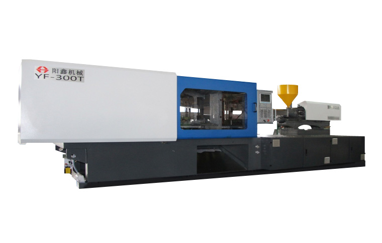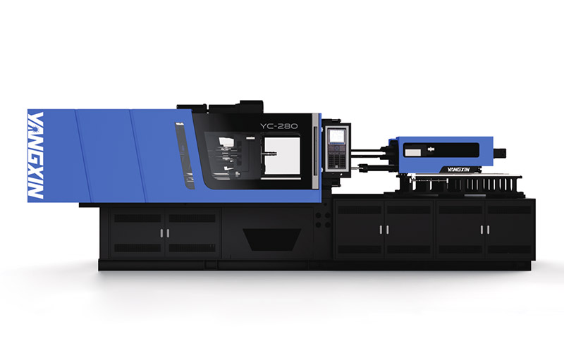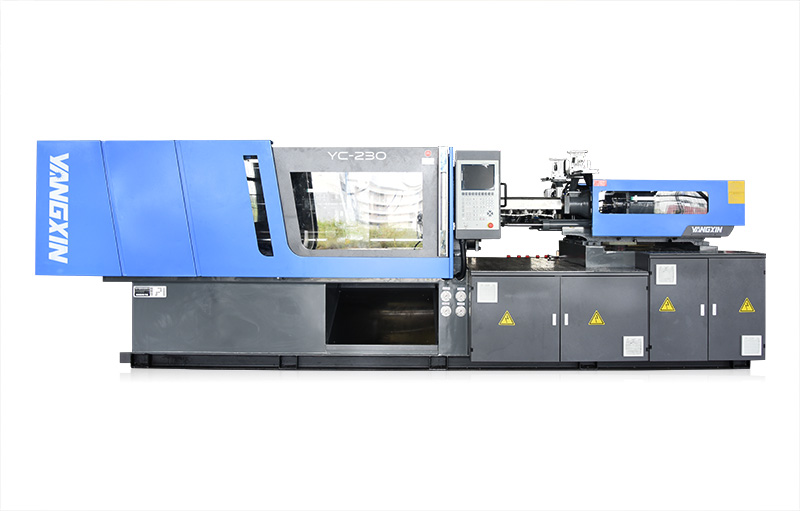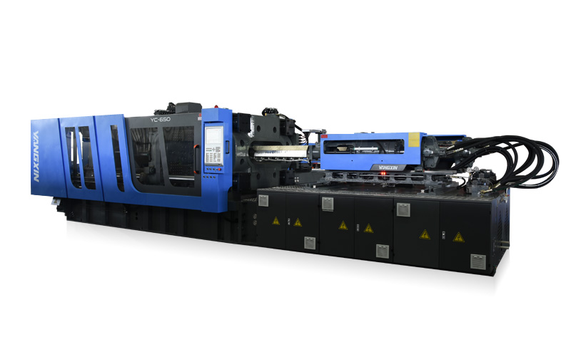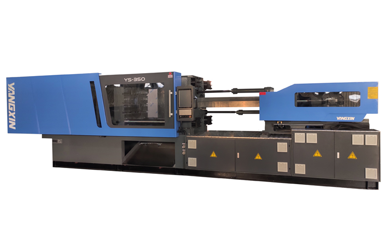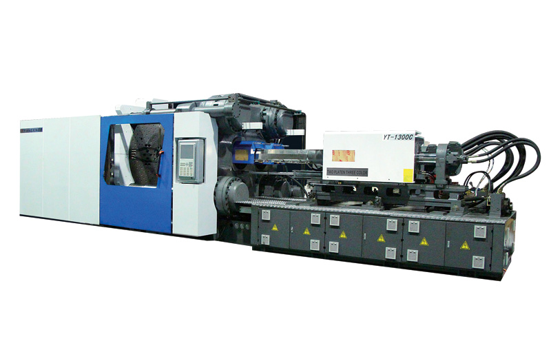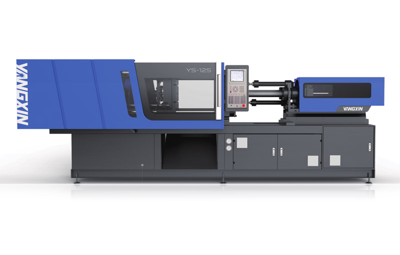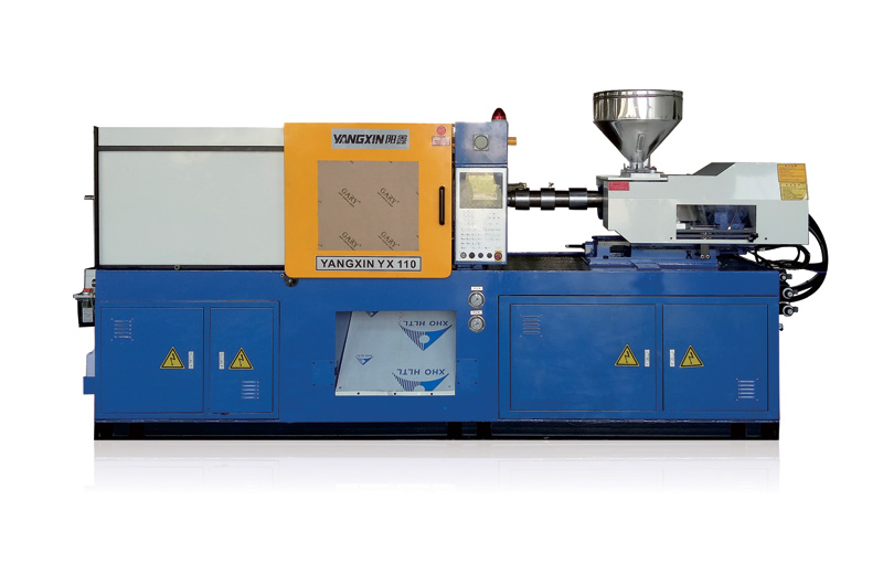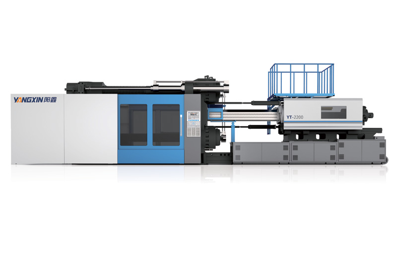
Precise locking system, outstanding efficiency, efficient servo drive, all meet all requirements. Focus on customer products, provide a complete set of technical solutions for customers, and create better investment returns and customer experience for global customers.
Energy efficient, precise and fast
With the lower cost of investment, we need to build a two plate machine with less room for production.
◆ The two-plate structure, shorten the length of the machine, and save 25-30% of the factory space.
◆ Quickly mold open/ close hydraulic cylinder and high pressure clamping hydraulic cylinder are respective, reducing the consumption of hydraulic oil to 50%.
◆ Mechanical more durable FEA design, box structure, less deformation of the platen.
◆ Respective mold clamping cylinder is not integrated with the platen, as a whole, without oil leakage problem by casting sand hole.
◆ Non-mechanism mold adjustment, less fault issue.
◆ Especial design on mold open force, only use 10% compare to mold closing force.
◆ Hydraulic clamping structure of two platen type can be quicker on mold mounting and dismounting. Simultaneously process ejecting function while mold opening, save the molding cycle time. ◆ Without contact between the tie bar and clamping cylinder, the movable platen does not affect the movement of the pison.
◆ The high pressure clamping screw nut can be completely locked in the quick process to clamping the mold, then the cycle time be shorten.
Space save
Mechanical more durable
More rapid production
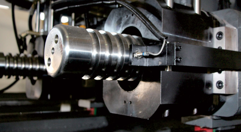
◆ With two diagonal cylinder fast movement, and with the baxe of the movable platen support by slipper guide keep the movable platen more stable, and the mold contact more precise.
◆ The moveable platen adopts linear sliding rail, which makes the motion more stable and the efficiency higher.
◆ In order to meet customer demand to increase the mold thickness and mold stroke, suitable for deep barrel mold.
◆ Can increase the platen size and the space between tie bar, according co customer needs, suitable for large mold;
◆ Cooperating with customer demand to modify the various combination on injection unit and clamping unit.
◆ Due to the tie bar and the cylinder piston are separated, not in conatct, easy maintenance.
◆ Respective clamping cylinder (not be casted together with stand platen), the oil seal can be replaced by whole set.
◆ The tie bar and the piston of the clamping cylinder are separated, The tie bar is not raquired to be removed when replacing the oil seal of the piston, and the cylinder is not required to be removed when replacing the tie bar.
More precise postioning
More flexibility
Easy maintenance

◆ Advanced two-platen clamping mechanism, simplified equipment, compact structure, can save factory occupied space.
◆ Since the zero friction between the tie bar and the movable platen, the service life is longer. Due to the two diagonal fast movement cylinder, the opening and closing speed has been improved greatly.
◆ Clamping pressure quick response, clasping force and main pressure are proportional, linear accurate.Pressure sensor real-time monitoring, and reproduce the hith precision of clamping force.
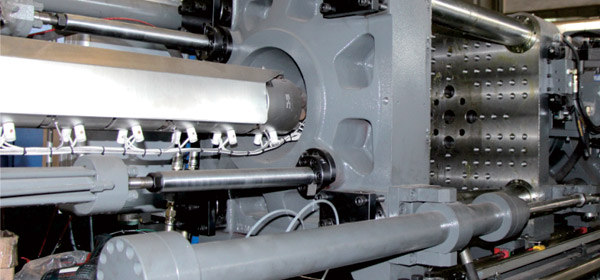
◆ By diagonal located, the high speed open/ close cylinder can shorten the cycle time.
◆ Synchronous pull rod brake device, adding brake cylinder with buffer function, make the brake performs accurately and smoothly.
◆ Support by slipper guide, the base of the movable platen not only ensure the precision of the production when mounting heavy molds but also improve the service ilfe of molds.
◆ Hith rigidity of the platen, uneasy to go deformation, which is beneficial to improve the life of the mold and the precision of the products.
MOLD CLAMPING UNIT
Reasonable space layout, long service life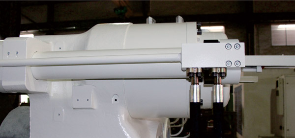
Accurate clamping
Rapid motion mechanism
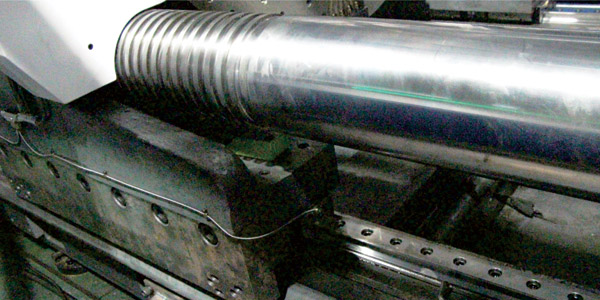
More durable slipper guide
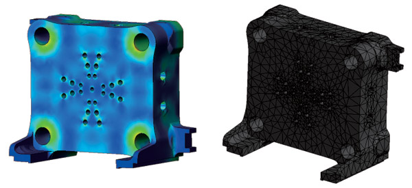
Hith rigidity plagen design
◆ Diagonal injection cylinder layout, the injection unit align to the center of the mold , to move smoothly;
◆ The mold clamping cylinder provide with compression control to perform the Injection compression function;
◆ The lineal rail guide, at the backside of the injection unit, has the advantages on low friction, fast response and smooth movement.
◆ With sliding pallet, the injection unit structure has high rigidity and the center of gravity of the injection unit is more accurate for moving smoothly.
INJECTION UNIT
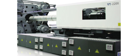
Fast and stable design
Low pressure injection technique
Hith efficiency and stable platen
High rigidity dtructure

TECHNICAL PARAMETERS
| Project | Unit | YT-1300 | YT-1600 | YT-1900 | YT-2200 | YT-2500 | YT-2800 | YT-3200 | YT-3700 | |||||||||
| Injection Unit | Screw diameter | mm | Φ110 | Φ120 | Φ120 | Φ130 | Φ130 | Φ140 | Φ140 | Φ150 | Φ150 | Φ160 | Φ160 | Φ170 | Φ170 | Φ180 | Φ180 | Φ190 |
| Theoretical shot weight | cm3 | 6411 | 7630 | 7348 | 8623 | 9486 | 11001 | 12463 | 14307 | 14660 | 16680 | 17684 | 19964 | 21212 | 23781 | 25180 | 28055 | |
| Shot weight of injection (ps) | gram | 5790 | 6890 | 6635 | 7787 | 8565 | 9934 | 11254 | 13069 | 13238 | 15062 | 15969 | 18028 | 19154 | 21474 | 22737 | 25334 | |
| ozs | 204.2 | 243.0 | 234.0 | 274.7 | 302.1 | 350.4 | 397.0 | 461.0 | 466.9 | 531.3 | 563.3 | 635.9 | 675.6 | 757.5 | 802.0 | 893.6 | ||
| Injection pressure | kg/cm2 | 2296 | 1929 | 1856 | 1582 | 2083 | 1796 | 2061 | 1795 | 1955 | 1718 | 200 | 1773 | 1935 | 1726 | 1948 | 1748 | |
| Injection rate | cm3/sec | 790 | 940 | 1052 | 1234 | 1088 | 1262 | 1100 | 1263 | 1377 | 1567 | 1472 | 1662 | 1640 | 1839 | 1760 | 1961 | |
| Clamping Unit | Mould clamping force | metrictons | 1300 | 1600 | 1900 | 2200 | 2500 | 2800 | 3200 | 3700 | ||||||||
| Mould clamping stroke | mm | 1510-2210 | 1750-2600 | 1750-2600 | 1850-2750 | 1950-2950 | 2250-3250 | 2200-3200 | 2300-3300 | |||||||||
| Daylight Max | mm | 2860 | 3300 | 3350 | 3550 | 3750 | 4150 | 4200 | 4300 | |||||||||
| Mould thickness | mm | 650-1350 | 700-1550 | 750-1600 | 800-1700 | 800-1800 | 900-1900 | 1000-2000 | 1000-2100 | |||||||||
| Distance between tie bar | mm | 1350*1100 | 1550*1400 | 1660*1450 | 1850*1550 | 1950*1650 | 2050*1750 | 2200*1850 | 2300*1950 | |||||||||
| Ejector stroke | mm | 300 | 300 | 350 | 350 | 400 | 400 | 450 | 450 | |||||||||
| Electrical Equipment | Max. Motor power | KW | 124 | 144 | 174 | 195 | 210 | 234 | 240 | 260 | ||||||||
| Temperature controller | (range)set | (0-400℃)*7 | (0-400℃)*7 | (0-400℃)*8 | (0-400℃)*8 | (0-400℃)*8 | (0-400℃)*8 | (0-400℃)*8 | (0-400℃)*8 | |||||||||
| Heater power | kw | 50.6 | 53 | 75.3 | 110.6 | 115 | 121.8 | 150 | 175 | |||||||||
| Others | Machine dimensions(LxWxH) | m | 10.2*3.3*2.8 | 11.3*3.5*2.9 | 13.3*3.7*3.3 | 14*4.1*3.4 | 14.3*4.2*3.5 | 14.8*4.3*3.6 | 15.3*5*3.8 | 16.5*5.3*4.1 | ||||||||
| Oil tank capacity | liter | 1800 | 2300 | 2800 | 3500 | 3500 | 4000 | 4100 | 4400 | |||||||||
| Machine weight | metrictons | 53 | 68 | 73 | 120 | 150 | 160 | 190 | 230 | |||||||||
| System pressure | kg/cm2 | 170 | 170 | 170 | 170 | 170 | 170 | 170 | 170 | |||||||||
APPEARANCE ADVANTAGE COMPARISON DIAGRAM
| The advantages of flexible layout and compact size are ideal for incorporating into your production environment. |  |
Note: The output of this product parameter is calculated according to the specific gravity of polystyrene of 1.05, assuming an efficiency of 0.88. As the product is continuously researched and improved, the design changes are subject to change without notice.

 >
>